
The IDG Podcast
Podcast References
Every document, chart, and source Chris and Sean reference on the show, organized by episode. We publish our formulas, assumptions, and coefficients so you can check the math yourself. Documents open in an on-page reader. If you find something wrong, tell us.
Episode 02 · September 2026
Mount Matters: Behind the Design of the Hesion Bow
Every suppressor mount is a cone pulled tight by a thread. Chris and Sean walk through why the Hesion Bow pairs a 15° taper, a ¼" axial taper length, a 7° buttress thread at 8 TPI, and six integral pawls as one coupled system, and what QD should actually mean.
Figures quoted in this episode
15°Taper angle
¼"Axial taper length (≈2× typical)
7° / 45°Buttress load flank / trailing flank
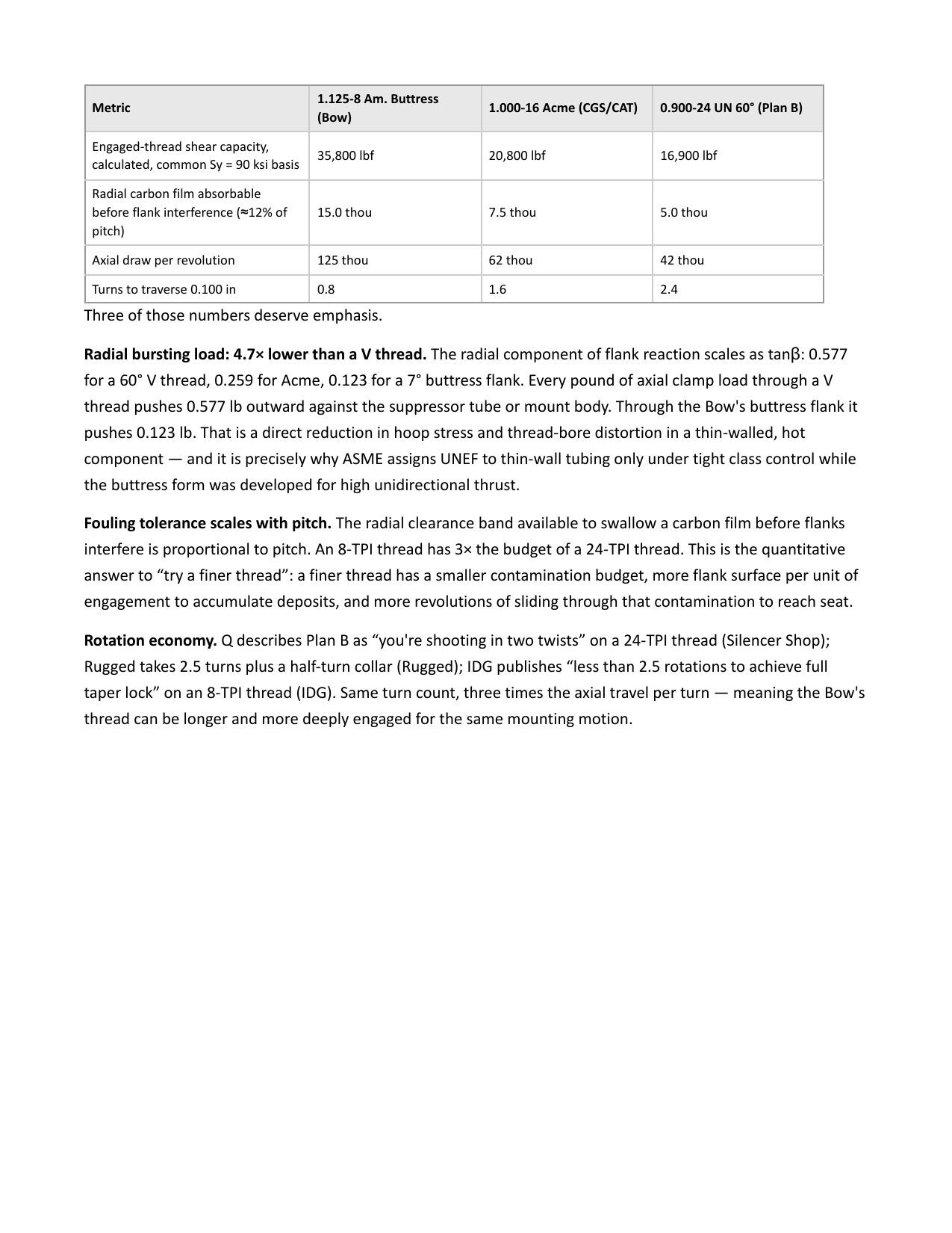
8 TPIThread pitch · ~2.5 turns to seat
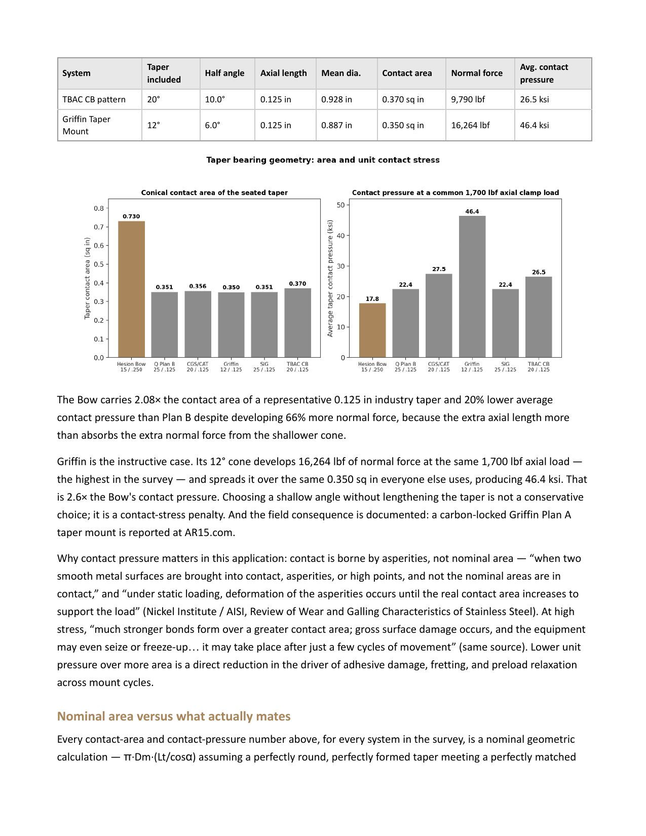
17.8 ksiTaper contact pressure @ 1,700 lbf clamp
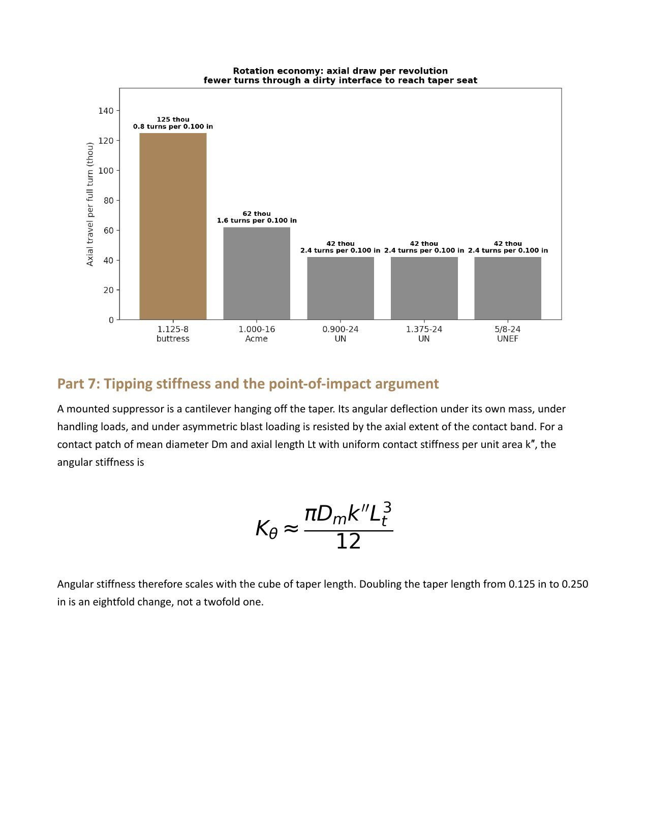
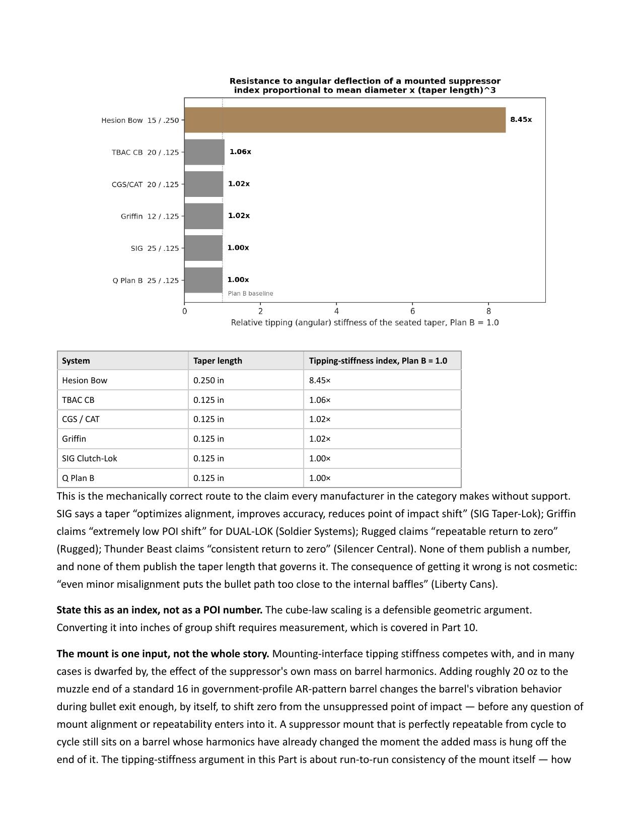
~8.4×Tipping stiffness vs. ⅛" taper (scales with L³)
6 / 32Pawls / ring teeth (non-divisible)
3,000Full on/off cycles in wear test
All values are defined, sourced, or flagged as assumptions in the white paper below. Where a coefficient of friction for Inconel-on-Inconel is used, it is an assumption based on typical nickel-alloy data and is labeled as such.
Referenced Documents
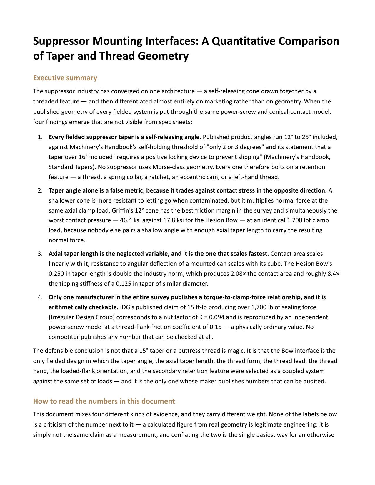
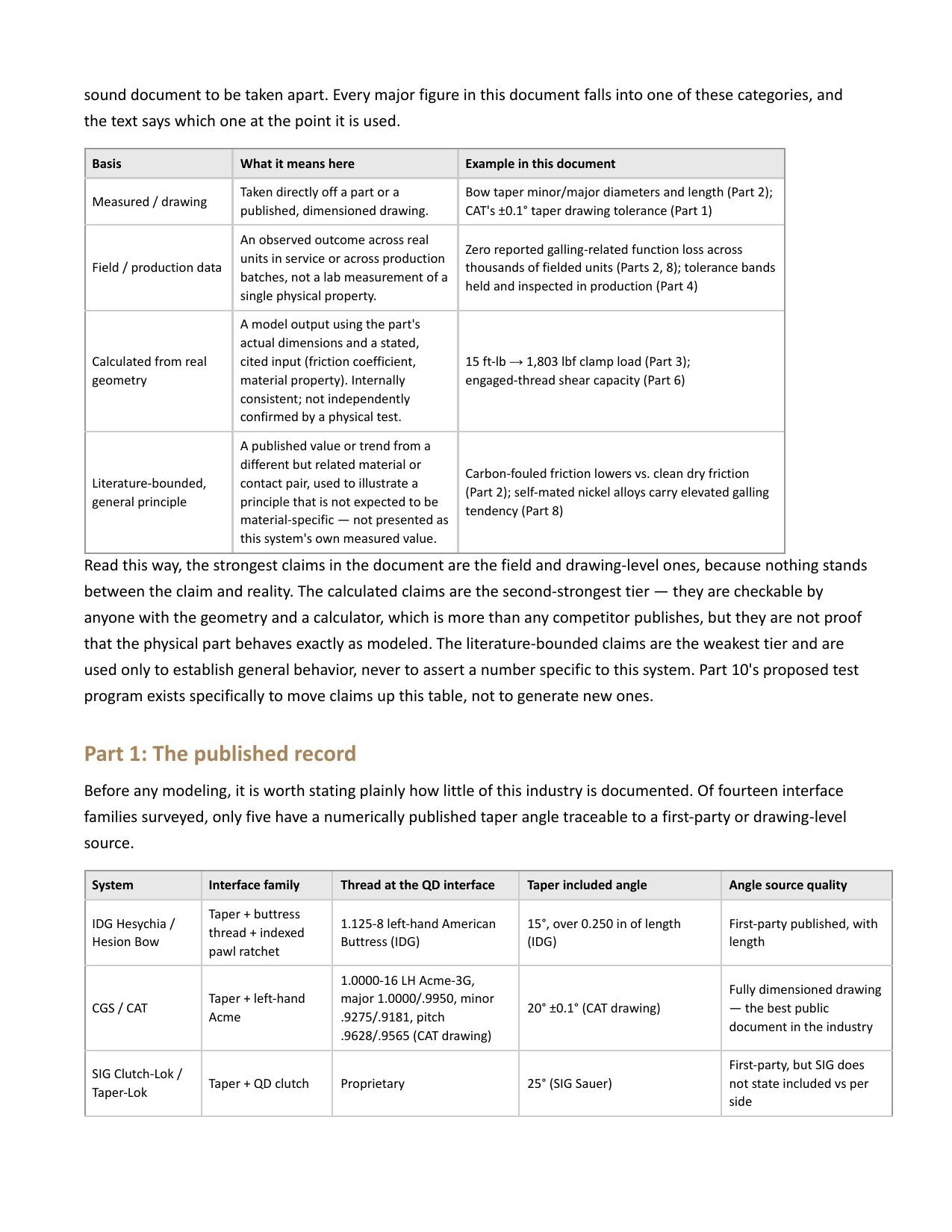
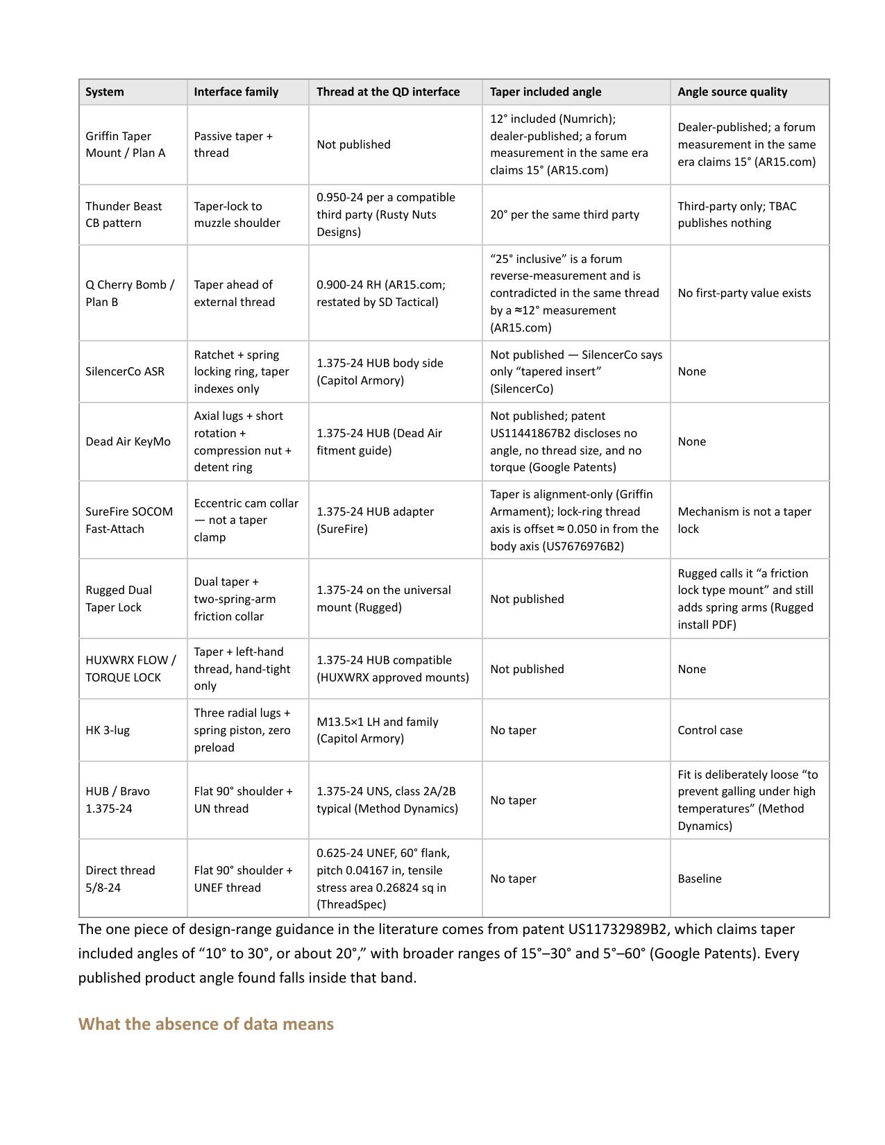
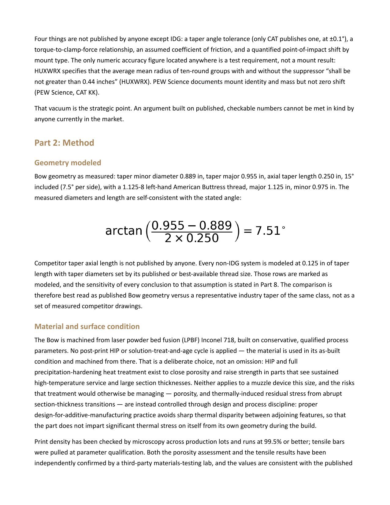
Suppressor Mounting Interfaces: A Quantitative Comparison of Taper and Thread Geometry
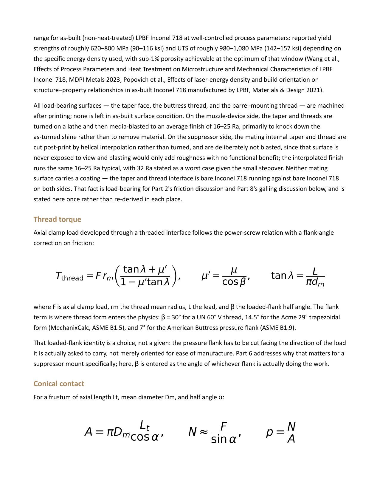
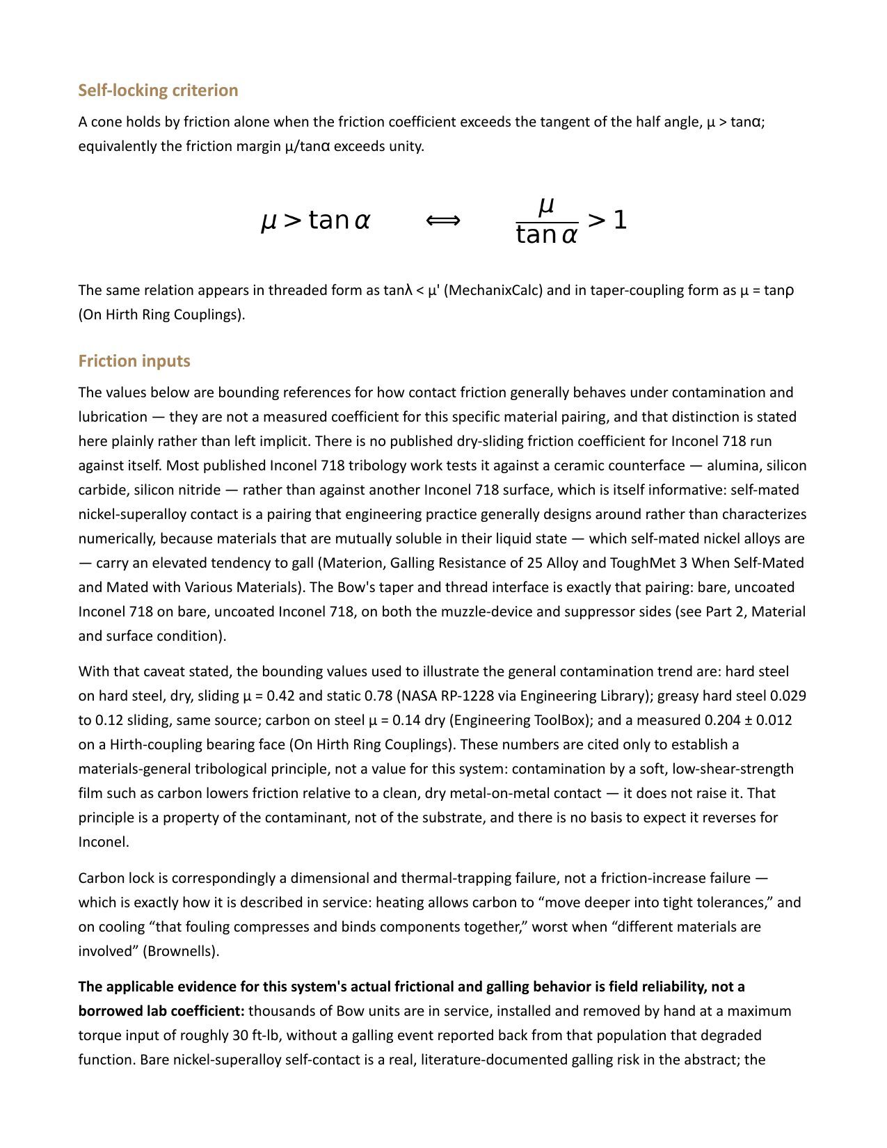
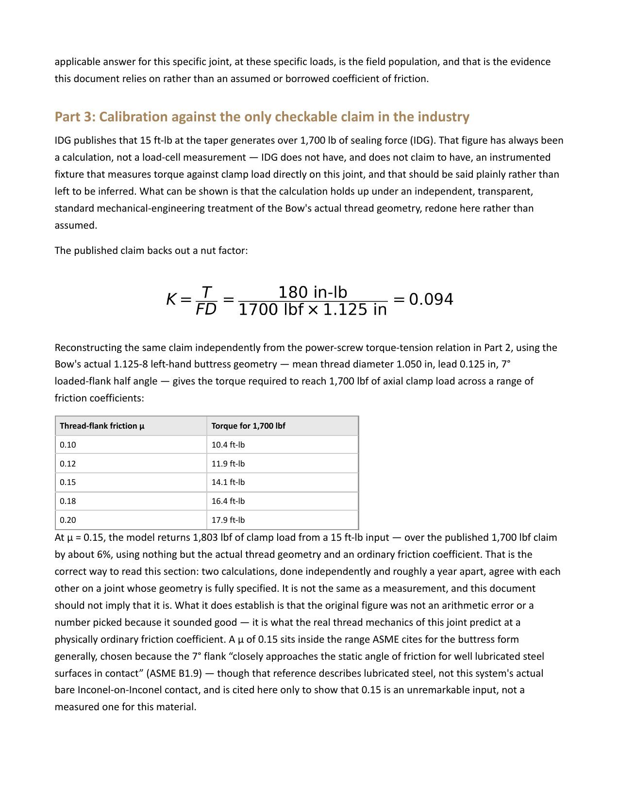
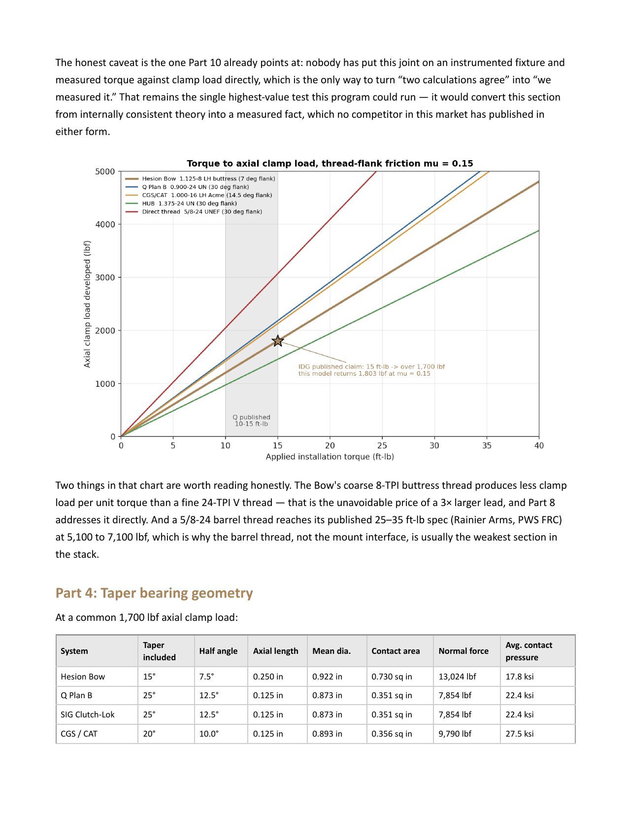
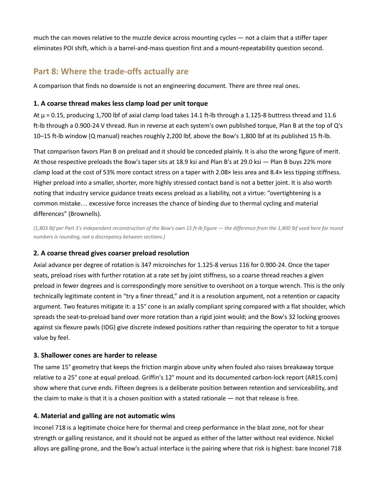
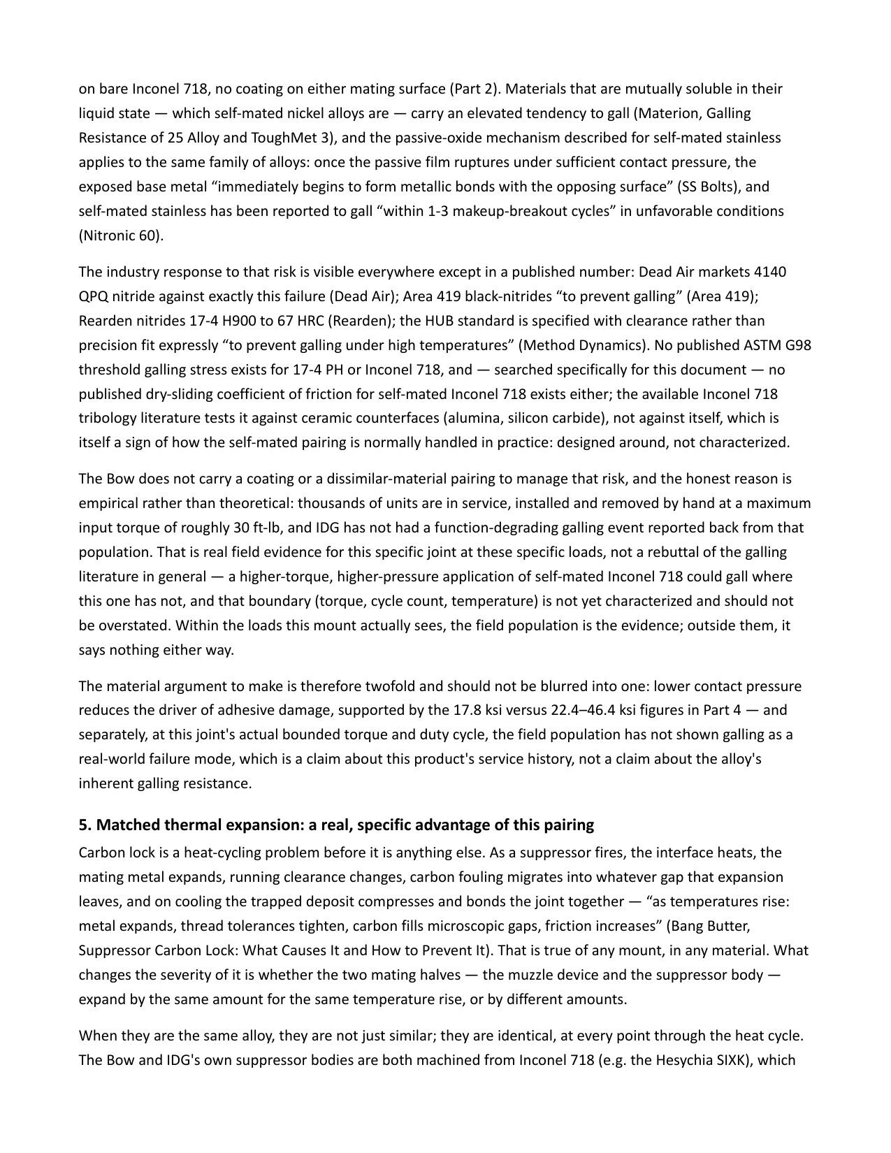
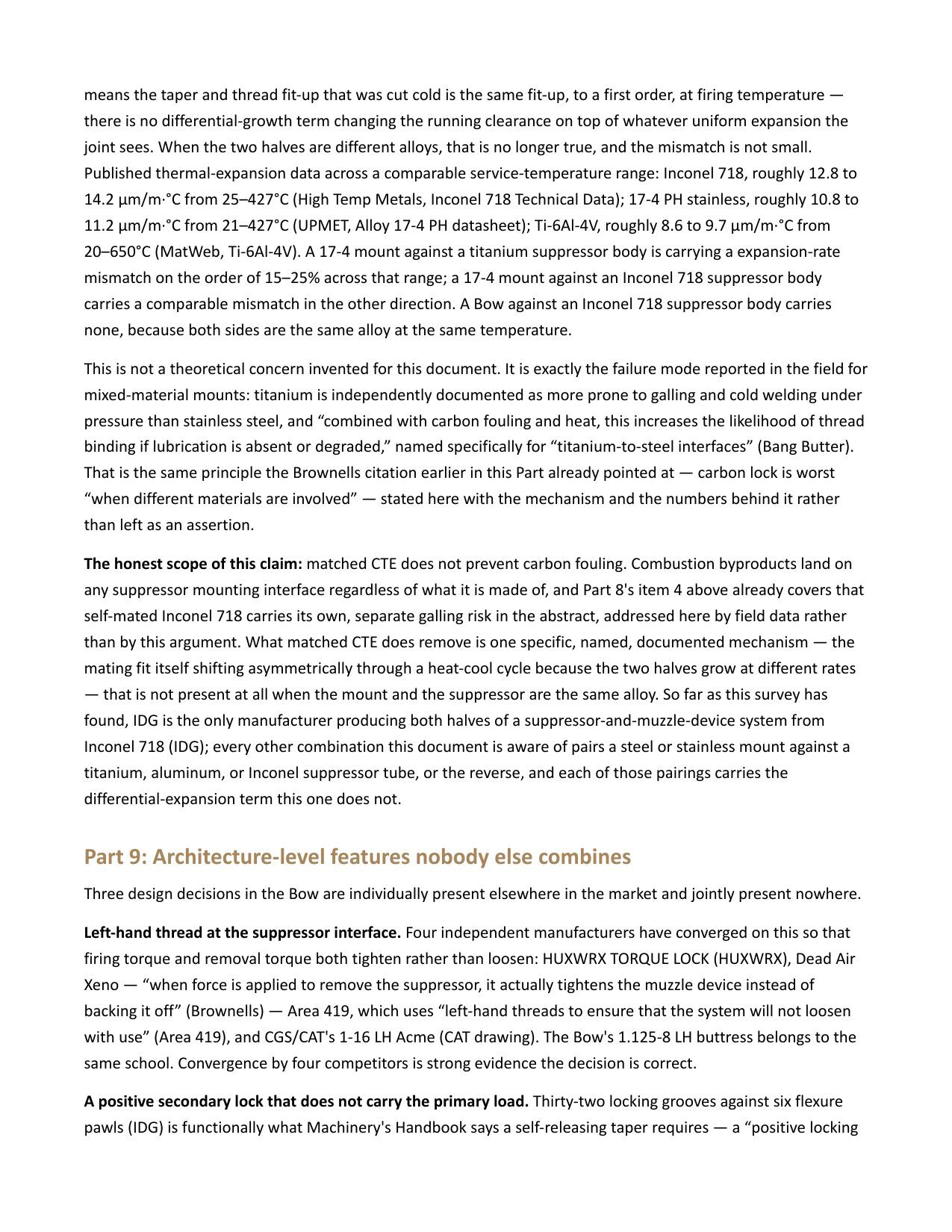
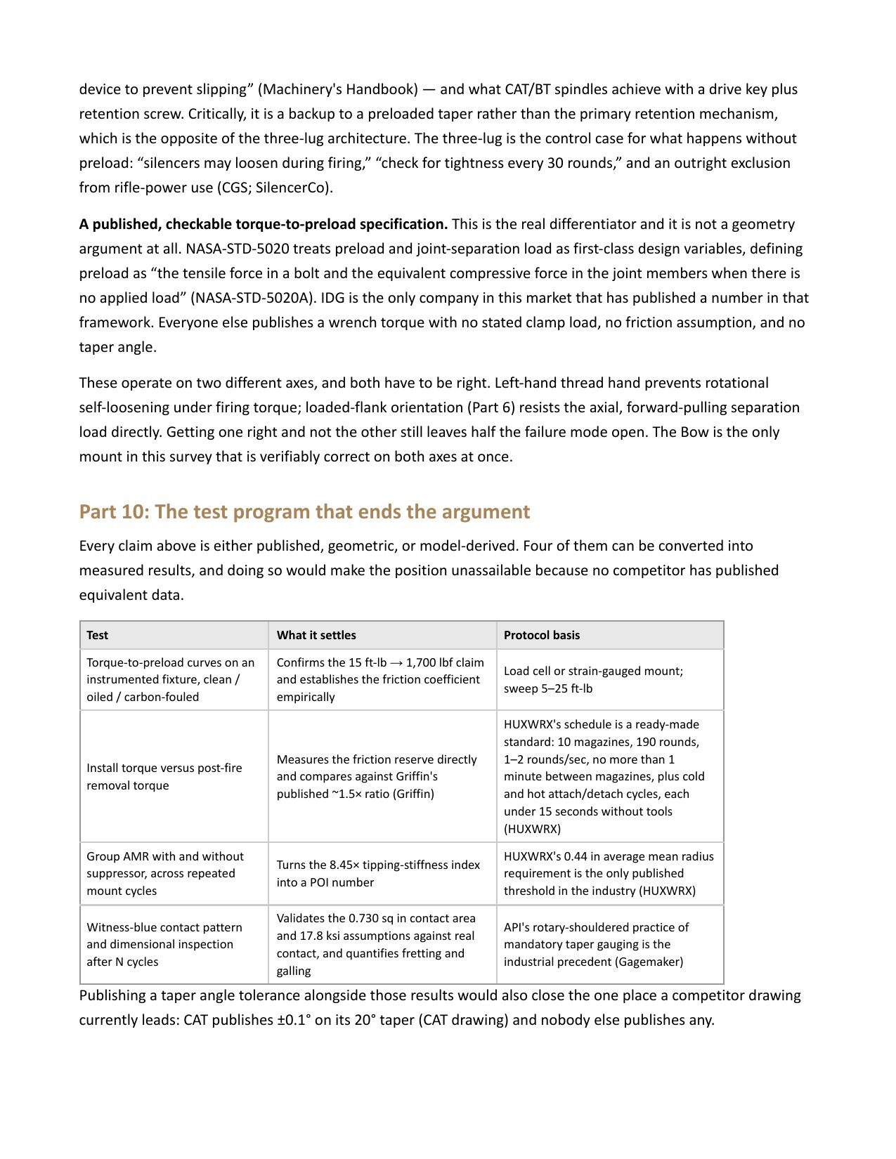
The document Sean reads from throughout the episode (Rev 3). Fourteen interface families surveyed against the published record, the power-screw and conical-contact model, calibration against IDG's 15 ft-lb to 1,700 lbf claim, taper bearing geometry, friction margin under clean and fouled conditions, buttress thread form, tipping stiffness, stated trade-offs, and the proposed test program. All charts shown on screen in this episode are drawn from this document.
Charts and demonstrations shown in the video
Contact pressure vs. taper angle
Same 1,700 lbf clamp load spread over different contact areas; why a shallower cone multiplies normal force.
Axial taper length and tipping stiffness
Contact area scales linearly with length; resistance to angular deflection scales with the cube.
Surface roughness and 70% taper engagement
Ra ~32 machined finish, why machine-tool tapers assume 70% engagement, and how carbon enters aberrations under heat.
Input pressure per square inch vs. competitors
Pop-up chart referenced during the carbon-lock discussion.
Thermal expansion bar chart
Matched Inconel pair vs. mixed-alloy mount and can through the same heat cycle.
Positive-lock threshold chart
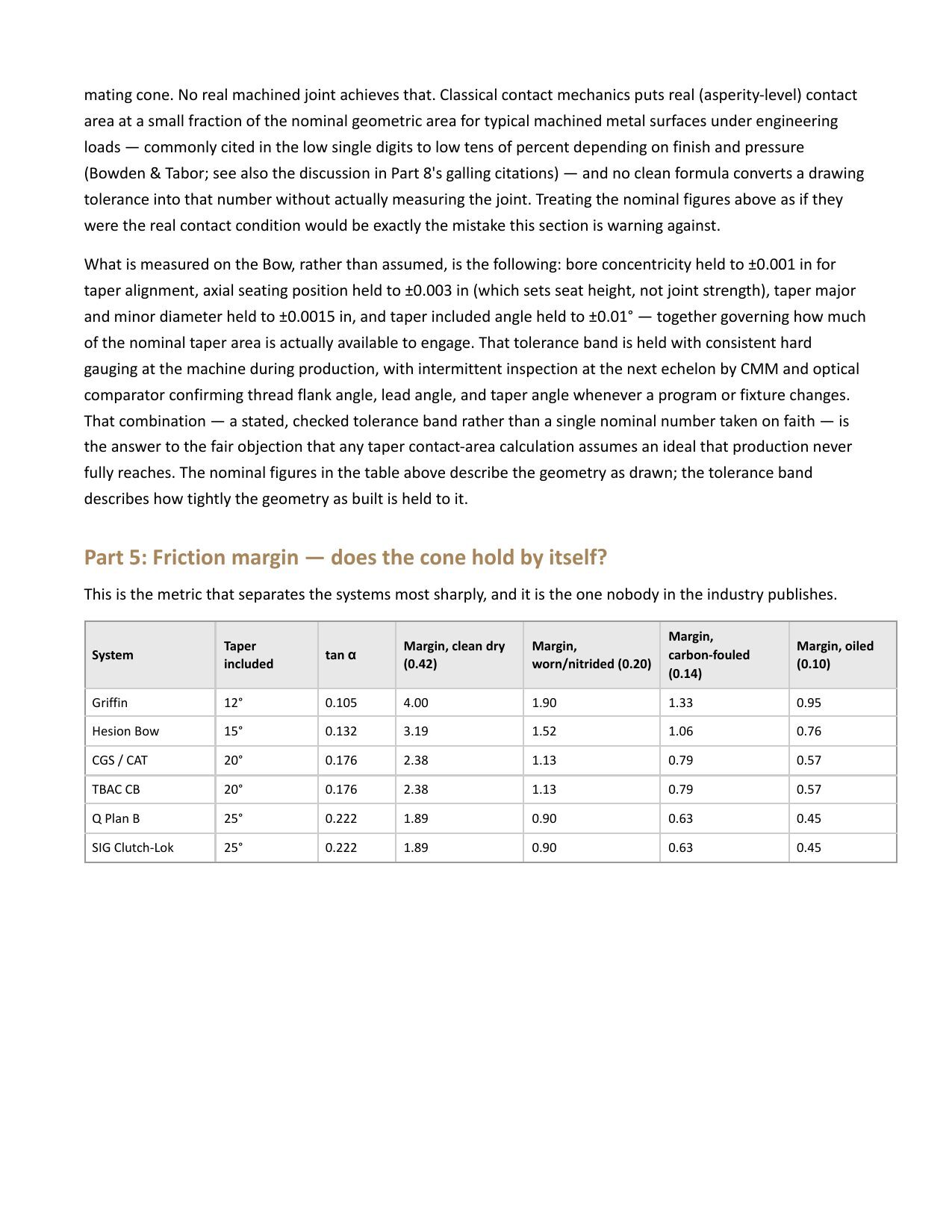
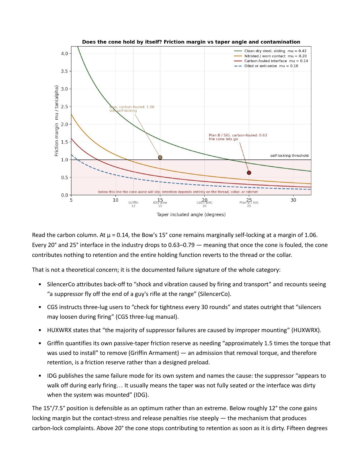
Dry / worn / fouled / oiled conditions against the 1.0 self-lock margin; the 16° self-releasing threshold from the Machinery's Handbook.
Pawl and ring geometry
Six compliant pawls on a 32-tooth ring; ~0.040" deflection; why radiused pawls are not a ratchet.
Buttress vs. 60° V-thread load path
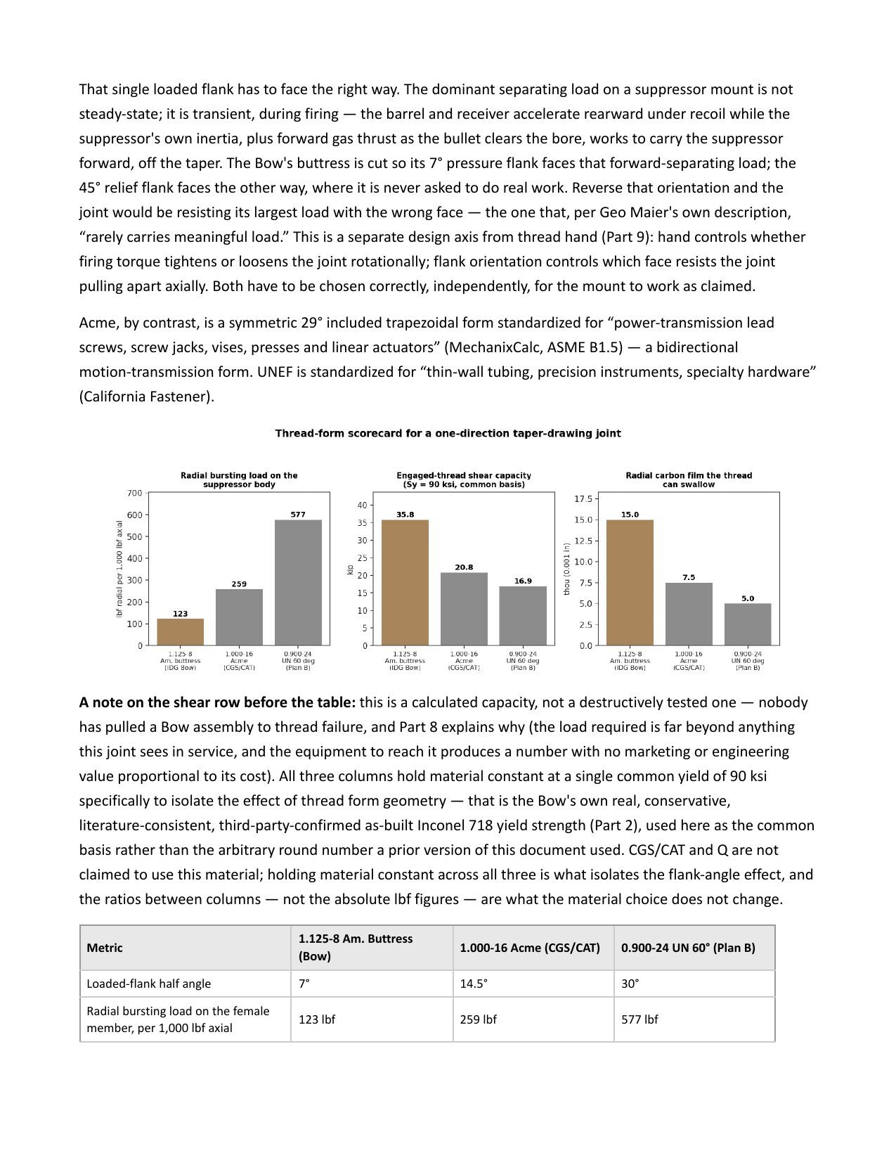
Radial displacement of a symmetric thread vs. the near-axial load path of a 7° flank.
Timestamps are approximate and refer to the YouTube edit.
External references cited
- Machinery's Handbook (Industrial Press). Taper and thread geometry, self-locking vs. self-releasing taper thresholds, buttress thread standards, and Morse taper data referenced throughout.
- Brownells, definition of carbon lock as "a dimensional and thermal trapping failure, not a friction-increase failure," read on air during the carbon-lock segment.
- Brian Ostos, customer video on return-to-zero and matched-material thermal behavior with the Hesion Bow.
- Blackstone Shooting Sports, range video showing carbon fouling stopping at the leading edge of the taper.
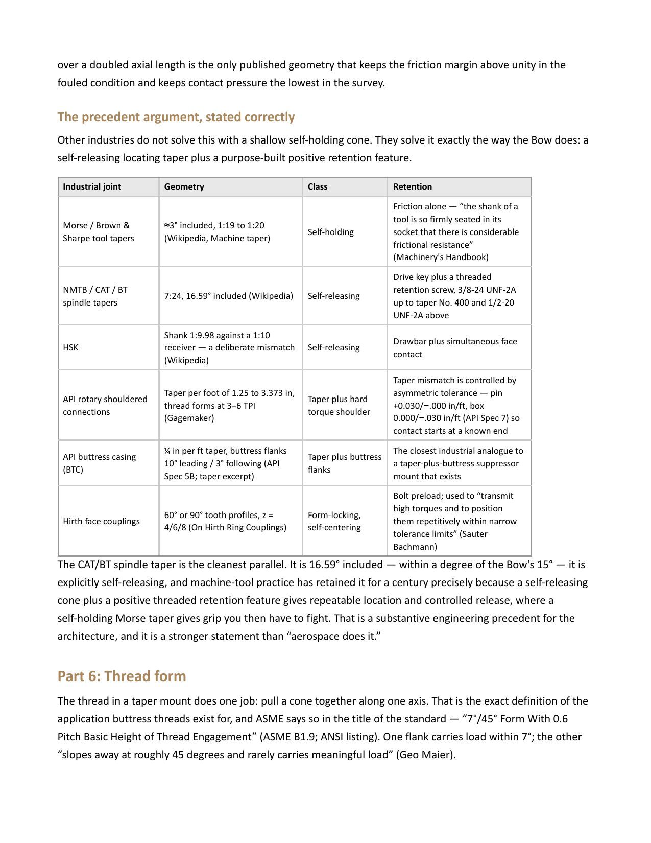
- Machine-tool taper standards (CAT 30/40/50, HSK) referenced as the model for repeatable concentricity through a drawbar-loaded taper.
Competitor systems discussed: Griffin Armament taper mounts, Q Cherry Bomb / Plan B, SIG ClutchLok, CGS, Thunder Beast CB, SureFire SOCOM, HUXWRX, and Dead Air KeyMo / 51-tooth are referenced for comparison only, using each manufacturer's published geometry and instructions where available. IDG has no affiliation with these companies, and nothing on this page should be read as a claim about the safety or quality of their products.
Corrections and stated assumptions
- Coefficient of friction, Inconel on Inconel: no published value exists for this pairing. The white paper uses an assumed value based on typical nickel-based alloy data, and flags it as an assumption.
- Surface-condition coefficients (dry, worn, fouled, oiled) are drawn from published studies of specific alloys and joint types and applied across the surveyed systems; the source and applicability are noted in the document.
- "Griffin 46.4 ksi" and "IDG 17.8 ksi" are calculated contact pressures at an equal 1,700 lbf clamp load using published cone geometry, not measured values.
- Wear test: 3,000 full on/off cycles on a Robodrill. Slight loosening in pawl engagement was observed near 1,000 cycles; the thread-and-taper joint continued to hold. Average user lifetime cycles were estimated at 280 to 350 from public forum and review data.
Episode 01 · 2026
Metal Matters: Inside 3D Printed Suppressors
Chris and Sean break down the material science behind suppressor design: density, weight, high-temperature strength, erosion resistance, thermal cycling, and flash suppression, with a close look at Inconel, titanium, and Haynes alloys and the manufacturing tradeoffs behind each.
Referenced Documents
PDF
Suppressor Alloy Comparison Sheet
Side-by-side properties for Inconel 718, Ti-6Al-4V, Haynes 282, and 17-4 PH stainless: density, yield strength at temperature, erosion resistance, and thermal-cycling behavior.
PDF
Why We Print Inconel
IDG's material-selection rationale for the Hesychia line, including weight-versus-durability tradeoffs and where titanium or Haynes would be the better choice for a different use case.
What was covered
Material Properties
Density and weight, high-temperature strength, erosion resistance, thermal cycling, and flash suppression, and how each translates to real-world suppressor performance.
Manufacturing
Production processes, material availability, precision, touch points, and design optimization, and how they affect consistency, longevity, and cost.
About
About the Show
Conversations on suppressor technology, firearms engineering, product development, and the decisions behind the products, hosted by Chris and Sean of Irregular Design Group.
The five steps behind every IDG design
- Question the requirements. Assume they're wrong until proven otherwise.
- Delete. If you aren't adding things back at least 10% of the time, you aren't deleting enough.
- Simplify. Only after the first two.
- Go faster. Iterate once the design is clear and lean.
- Automate. Last, and only when the process is proven.
A product made for everybody is a product for nobody. When we compare the Hesion Bow to other systems, we are talking about our use case. Different mounts exist for good reasons, and we entered the market after a lot of real innovation had already been done.
Provided for viewing only. © Irregular Design Group, LLC. Reproduction or redistribution without written permission is prohibited.